Laser Engraver

SUPERSPEED-660

The maximum printable area for this laser engraver is 806 x 450 mm.

Method 1: Export to AutoCAD as DXF file (geometry only). This option allows you copy/paste, move objects, and select different settings more easily.

Method 2: Use the SUPERSPEED-660 template in Inventor. This option allows you to work entirely in Inventor.

AutoCAD Layers

WhiteLayout (does not plot)
RedCutting Vectors
MagentaSecond Cut (used for acrylic)
BlueVector Engraving (outlining)
GreenDeep Engraving
YellowLight Engraving
CyanUsed for custom settings
OrangeUsed for custom settings

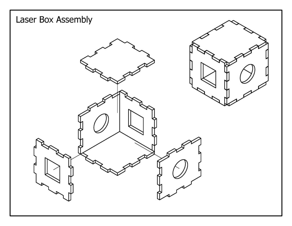
Sizing Tabs for Joints

Use a 0.7mm difference in size between the male and female sides of the joint.

The male side should be 0.7mm larger, but still centred with the female tab.

Note: With the previous laser engraver, we used 0.5mm because the width of the laser was smaller.

Method 1: Inventor to AutoCAD

Method 2: Plot from Inventor

Cutting Circle Holes for Square Axles

3mm x 3mm square axles will spin freely in holes that are designed with a 4.1mm diameter.

4.0mm holes will work for a tighter fit, but may require you to file down the edges.

Power Settings for Chipboard

Cutting
(vectors)
20% Power
10% Speed
Engraving
(vectors)
30% Power
50% Speed

Engraving MDF for Depth

Medium Depth
(raster)
100% Power
80% Speed
Deepest Level
(raster)
100% Power
40% Speed

Additional Materials

Card Stock
(vectors)
20% Power
10% Speed
6mm MDF
(vectors)
100% Power
1% Speed

Common Sizes for Press-Fit Joints (Acrylic Gears)

SUPERSPEED-660 Power & Speed Settings

LayerColourPlottingPowerSpeedPPI
LayoutWhite/BlackNo Plot0%80%500
CuttingRedVector60%2.5%500
Second CutMagentaVector30%3%1000
Vector EngraveBlueVector10%10%1000
Deep EngraveGreenRaster50%80%500
Light EngraveYellowRaster20%80%500
Misc 1CyanVect/Rast50%50%500
Misc 2OrangeVect/Rast50%50%500