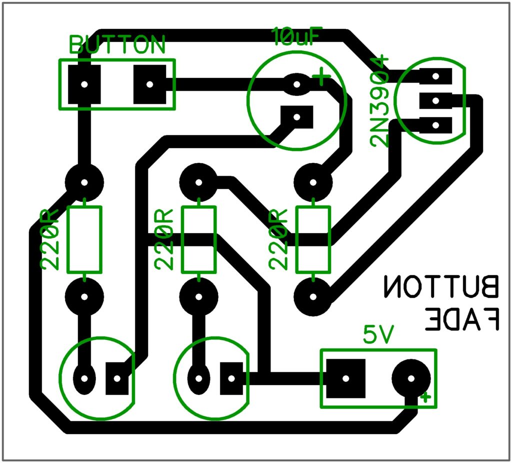
Button-Fade PCB


Questions
1. Why do the LEDs each have a 220R resistor?
2. When the button is pressed, why does the second LED turn on?
3. When the button is released, why does the LED fade slowly instead of suddenly turning off?
4. There is no current flowing through the 10uF capacitor, so why does the negative side need to be connected to ground?
5. Rather than powering the LED directly from the 10uF capacitor, why is the transistor needed to create a visible fading effect?
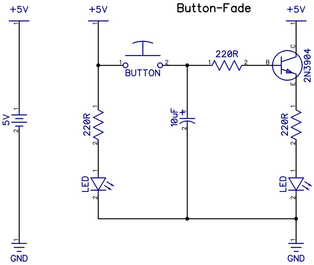
Schematic
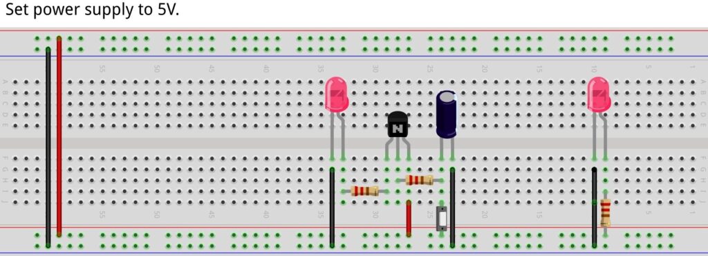
PCB
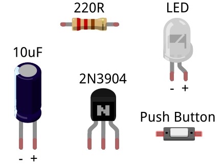
Components
The resistors (220R) and push button have no +/- pins because they are non-polar.
The LED, capacitor (10uF), and diode (1N4001) all have markings on the negative pin, which always goes in the square hole on the PCB.
The NPN transistor (2N3904) has one flat side to indicate direction. Use the PCB diagram to ensure the flat side is in the correct orientation.